How to Adjust your Cell Phone Repeater DIP Switches
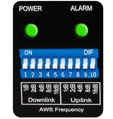
To achieve the maximum coverage area of your wireless repeater system, the end user's aim is to obtain the maximum Downlink (DL) Gain without sending the system into alarm. There are 2 LED’s for each frequency bank (Power & Alarm). The POWER LED is on the left, and the ALARM LED is on the right and changes color from GREEN, to AMBER, to RED or OFF depending on the severity of the interference.
The alarm LED colors indicate as follows:
GREEN = No Interference
GREEN / AMBER Flickering = Mild Interference
SOLID AMBER = Moderate Interference
RED = Severe Interference
OFF / NO LIGHT = MUTE, Circuit Shut-Down Enabled
After the system is setup and powered ON, check to make sure all the alarm LED's are solid green. If not solid Green on all switch banks, be sure to take the respective bank/s out of the alarm error state as soon as possible.
When an alarm is present, please attenuate the gain in increments of 2dB till the alarm is removed. To add attenuation, you need to move the DIP switches to the ON or UP position. Each switch number corresponds to an attenuation value. The total amount of attenuation set corresponds to the total value of the DIP switches that are in the ON position.
You will first add attenuation on the DL side (Switches 1-5) and then match the same values on the UL side (Switches 6-10) to make sure your system does not cause interference back to the cell tower.
PLEASE NOTE: If any of the alarms go into MUTE or OFF, this is because of severe interference. You will first need to add attenuation (Typically more than 2dB) then power cycle the repeater using the ON/OFF Switch to take it out of the MUTE state (OFF then back ON). If the respective alarm LED is still OFF, then continue to add more attenuation and repeat the sequence of power cycling the repeater after each adjustment is made till the alarm LED turns solid green. If you suspect you have added too much attenuation, start to remove attenuation till the repeater just about goes into alarm, then add back 2dB of attenuation as a good setting. Remember to match the UL with the DL.
Some repeater systems are also equipped with a pre-amplifier which also has an alarm monitoring feature for the uplink path. The end user should also ensure the alarm LED's on the pre-amp are solid green at all times. If not green, this typically is an indication of another booster nearby that is over-driving the uplink path of the system. DO NOT leave the system ON for an extended period of time if this is so as it will eventually cause internal damage to your repeater system. Either try to shut down the interfering booster or relocate the service antenna away from the interference source.
To determine the cause of your alarm LED showing an error, you can disconnect the indoor antenna / service line from the “INDOOR” port of the repeater.
If the LED does not change to green, then it's either a case of the input signal after passing through the pre-amp is now too strong or there is another antenna within a few feet of your donor antenna that's causing the interference.
If there are no other antennas close by, at this point you must attenuate the downlink DIP switches by 2dB increments till the LEDs turn green again. (Switches 1-5) After this, you must match the same attenuation value on the uplink side (Switches 6-10). Once complete, please reconnect the indoor antenna / service line again. If after connecting the indoor service line the alarm LED changes back to amber or red then signal oscillation is taking place.
Signal oscillation (OSC) is the result of your indoor and outdoor antennas being too close to each other and should be separated more or oriented away from the donor antenna. If you have confirmed your donor and service antenna placements are in optimal locations and the repeater is still in alarm, you then need to add more attenuation by 2dB increments till the LED's turn green again. Remember to rematch the uplink value to the downlink.
Try making some test calls throughout the desired area of coverage while monitoring the LEDs to see if it they chance color. If you are showing strong signal strength but your calls are not going through, it could be that you need to attenuate your uplink a bit more than the downlink.
Keep in mind however that you do not want to have more than a 4-5dB difference between the uplink and downlink values for optimum system performance.
If you need to add excessive uplink attenuation, it could be the result of another signal booster nearby your service antenna causing uplink interference with your system. Sweep the area to confirm there are no other boosters in operation nearby. (Stationary or mobile)
Feel free to call or email us when commissioning your repeater system to make sure you have seamless integration to the cellular network. We are always happy to help.
CLICK HERE FOR PDF COPY
Drop File